To receive a free PDF copy of The Fundamentals of Electrocardiograph Interpretation by Harry Mond, subscribe to his email blog by entering your email address below.
Thank you! Your submission has been received!
Oops! Something went wrong while submitting the form.
Purchase the textbook
Purchase a hard cover or paperback copy of The Fundamentals of Electrocardiograph Interpretation by Harry Mond on Amazon.
As a non-invasive electrophysiologist, I have always had a problem understanding AVNRT. As a result, I set out to create a “Fun with ECGs” that explained the ingredients required to initiate and maintain the arrhythmia.
As its name implies, AVNRT is a reentrant junctional or supraventricular tachyarrhythmia which involves the fast and slow pathways within the AV node creating a self-perpetuating circus movement. It can be divided into typical (slow-fast) or atypical (fast-slow) as well as several rarer forms related to more than one slow or fast pathway with similar electrophysiological properties. On the ECG, they can be identified and differentiated by the positioning of the P wave in relation to the QRS complex, which in turn is related to the direction of the re-entrant AV nodal circuit. However, in about 60% of cases, the P wave is buried in the QRS/T and cannot be identified on the surface ECG.
Typical AVNRT (slow-fast)is by far the most common of the junctional tachyarrhythmias (>80%) and frequently occurs in young, otherwise healthy females. It starts abruptly, often provoked by dehydration, exertion, caffeine or alcohol. The tachycardia is frequently initiated by premature atrial ectopy which finds the fast pathway refractory and conducts anterograde via the slow pathway. With an echo beat, a reentry circuit may be created. The term slow-fast describes its movement in the AV node. The ventricular rate of these tachycardias is dependent on the electrical properties of these pathways and is usually in the range of 140 to 260 bpm.
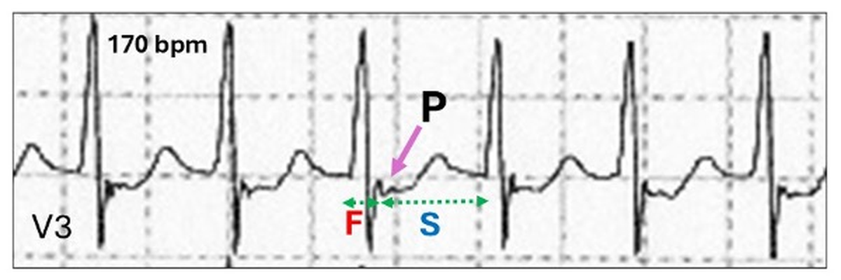
On the ECG, the retrograde conduction to the atrium resulting in an inverted P wave is via the fast pathway (F) and hence the R-P timing is short. Consequently, the P wave may be embedded within or just beyond the QRS, creating a “pseudo” wave (P).
Apart from critical timing, to create AVNRT, the following AV nodal electrophysiologic properties are necessary:
Dual AV nodal pathway physiology
Retrograde conduction
Echo beats
Let us discuss these in order.
Dual AV nodal pathway(s) physiology or simply dual AV nodal physiology results from two ill-defined extensions of the AV node creating different pathways for the propagating wave of depolarization, linking the atria and ventricles. These pathways are very familiar to the interventional electrophysiologist, but otherwise poorly understood by general cardiologists. Although, probably present in all human hearts, they are only occasionally recognised on the ECG as the cause of PR extension, retrograde VA conduction, echo beats and reentry tachyarrhythmias. One of these, the fast pathway lies within the anterior section of the triangle of Koch, whereas the other, the slow pathway lies adjacent to the coronary sinus and posterior tricuspid annulus.
Their electrophysiology characteristics are as follows:
Fast pathway: Faster conduction velocity but slower to recover, due to a longer refractory time.
Slow pathway: Slower conduction velocity but quicker recover, due to a shorter refractory period.
As the normal wave of atrial depolarization propagates from the sinus node in an inferior direction, it approaches the AV junction at multiple sites and enters both pathways. Because the fast pathway has a shorter conduction time, it reaches its distal connection and commences retrograde concealed depolarization of the terminal portion of the slow pathway, rendering it refractory. The result is the “normal” PR interval.
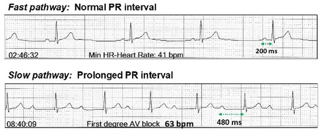
In those patients whose ECGs are able to demonstrate slow pathway anterograde AV conduction, it is possible to create scenarios where the fast pathway blocks because of its longer refractory period allowing transfer of conduction to the slow pathway resulting in the abrupt appearance of a longer PR interval with a range of 350 ms to 550 ms.
At night, the sinus rate is slower, and conduction is via the fast pathway with a 200 ms PR interval. During the day, the fast pathway may block as a result of the faster sinus rate and conduction is via the slow pathway with a 480 ms PR interval.
Should the prolonged PR interval with slow pathway conduction be called first degree AV block as the changes are physiological? This change in PR interval may not be recognised as slow pathway conduction and it is thus important to observe the abrupt change in PR interval to confirm the transfer of conduction from one pathway to the other. Again are these changes autonomic nervous system influenced (extrinsic) or maybe pathology in the fast pathway (intrinsic)? In most cases, where dual AV nodal pathways physiology is demonstrated, the fast pathway conduction is 200 ms or more suggesting some intrinsic disease may be required to trigger slow pathway conduction.
To recognize the transition on the ECG, it is important to understand the factors that allow slow pathway activation (onset) or reversion back to fast pathway conduction (offset).
Slow pathway conduction onset:
The transition from fast pathway to slow pathway assumes fatigue in the fast pathway usually due to increase in the heart rate and shortening of the P-P interval or atrial ectopy. Sometimes there are no obvious triggers.
No discernible change in the sinus rate.
Atrial ectopic.
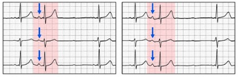
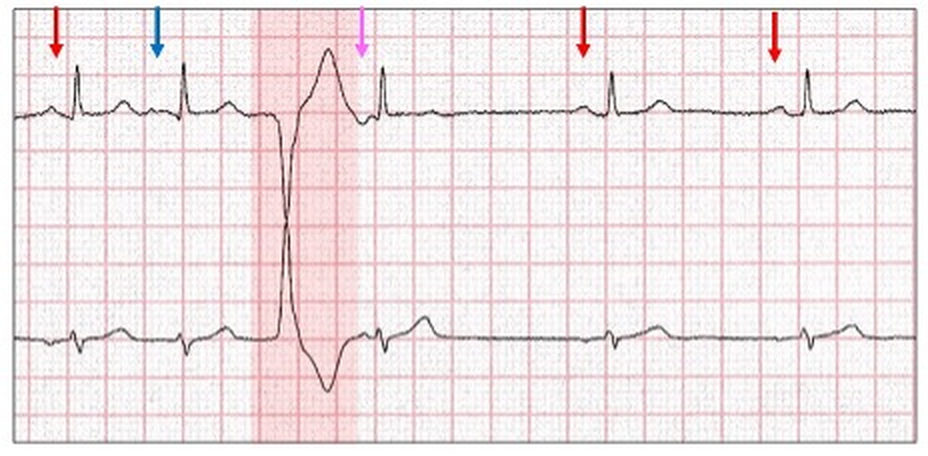
Because of the short coupling period, the atrial ectopic (blue arrow) would normally be non-conducted because of a refractory fast pathway. The ectopic now conducts through the slow pathway. An alternate explanation: AV conduction remains partially refractory.
Ventricular interpolation.
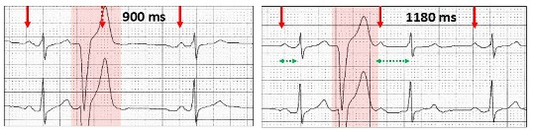
Left: Ventricular ectopic with compensatory pause and non-conducted concealed sinus P wave (red stippled arrow). Right: As the sinus rate slows, the sinus P wave is now visible following the ectopic T wave and conducts to the ventricle as an interpolated ventricular ectopic beat. Because the fast pathway is still refractory from the ventricular ectopic, there is slow pathway conduction for that one beat only. An alternative explanation as above.
Wenckebach AV block
Sinus rhythm (red arrows) with probable atypical 3:1 Wenckebach AV block (high degree AV block). There is fast pathway conduction (F), a dropped beat (red stippled arrow) and the next beat is now conducted via the slow pathway (S).The sequences are repeated.
Slow pathway conduction offset:
The return to fast (normal) AV conduction requires a slowing or pause in the sinus rate.
Nocturnal heightened vagal tone.
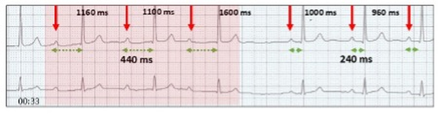
Sinus rhythm with slow pathway AV conduction. There is abrupt sinus slowing, allowing fast pathway conduction (240 ms) to recover.
Sinus pause (yellow highlight).
Slow pathway conduction (440 ms). A sinus pause or heightened vagal tone allows fast pathway conduction (240 ms) to recover.
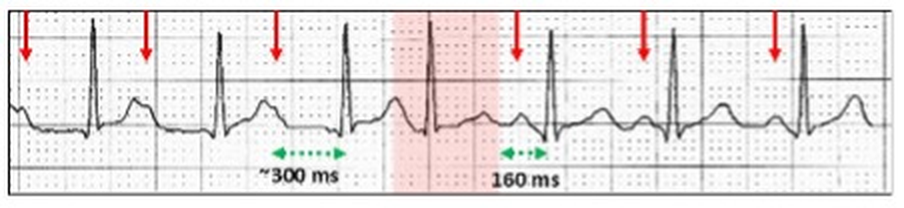
Junctional ectopic (red highlight).
Slow pathway conduction (300 ms). A junctional ectopic (red highlight) does not penetrate the fast pathway allowing the next AV conduction after a pause to conduct via the fast pathway (160 ms).
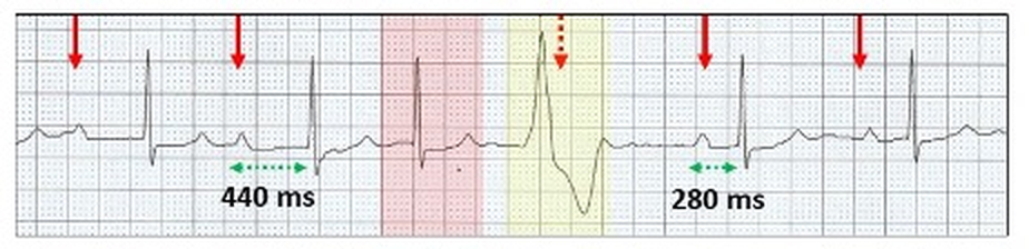
Ventricular ectopic compensatory pause.
Slow pathway conduction (440 ms). A junctional ectopic (red highlight) is followed by a ventricular ectopic (yellow highlight) and the compensatory pause allows fast pathway conduction (280 ms) to recover. There is long pause in AV conduction.
Slow pathway conduction (400 ms). An end diastolic interpolated ventricular ectopic (yellow highlight) lies in the PR interval. Because of the pause in AV conduction (red stippled arrow), fast pathway conduction (200 ms) recovers.
Wenckebach AV block pause.
Wenckebach AV block (red highlight) with dropped P wave (red stippled arrow). The next attempted Wenckebach sequence has no dropped beat (purple stippled arrow) but reversion to slow pathway conduction (yellow highlight, 540 ms). Fast pathway conduction is restored (blue highlight) following the next non-conducted sinus P wave (red stippled arrow).
Retrograde conduction implies conduction from an ectopic site to the atrium via the AV node or accessory pathway. II results in a P wave configuration which differs from an anterograde P wave, and in most ECG leads is inverted. The site from where the impulse originates can be the AV node, Bundle of His, distal conducting system or the body of the ventricles including ventricular pacing. On the ECG, the QRS complex usually precedes the inverted retrograde P wave but on occasion may follow it.
There is controversy as to whether anterograde and retrograde conduction use the same AV pathways. Although dual AV nodal pathways may play a role, some authorities believe that within a pathway, there are separate anterograde and retrograde channels. This might explain why bidirectional AV conduction may not have the same timing. When AV nodal disease is present, it becomes more complicated. For instance, with complete AV block, there is no anterograde conduction but in about 10% of cases, retrograde conduction is possible.
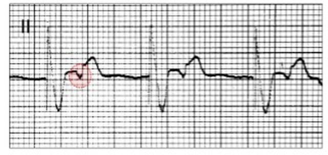
VVI pacing in a patient with sinus bradycardia and complete AV block. There is retrograde conduction to the atrium with each paced beat (red oval).
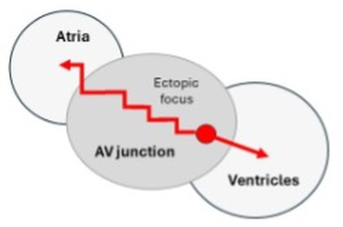
The two main sites for the ectopic focus that results in retrograde conduction are the ventricles and AV junction.
Ventricular ectopy
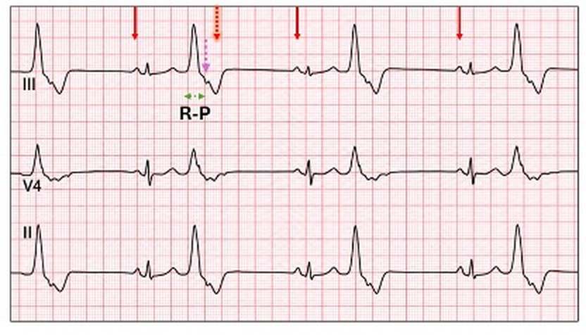
With ventricular ectopy and VA conduction, the inverted P wave lies in the ST segment or T wave of the ectopic with the timing of the conduction being from the onset of the QRS to the commencement of the P wave or where it is best recognised. The timing is referred to as the RP interval. It is not always easy to recognise these P waves, which are frequently mistaken for non-conducted sinus P wave.
Ventricular bigeminy with retrograde P waves (purple stippled arrow). The inverted P wave is earlier than the next scheduled sinus P wave (shadowed stippled red arrow).
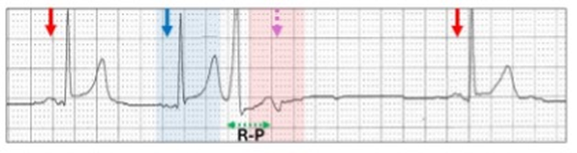
When retrograde conduction is delayed, there is a long RP interval (first degree VA block) and the inverted P wave may emerge from the ectopic T wave and easily identified.
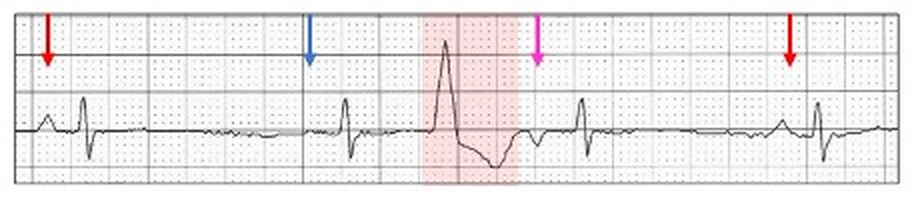
Sinus rhythm (red arrows) with a possible junctional ectopic (blue highlight, blue arrow) followed by a narrow QRS ventricular or fascicular ectopic with retrograde conduction (pink stippled arrow) and a prolonged R-P interval. The earlier junctional ectopic may result in a refractory fast pathway, allowing the retrograde conduction from the ventricular ectopic to conduct via the slow pathway, resulting in a prolonged RP interval.
Ventricular arrhythmias
Retrograde conduction can be recognised with ventricular arrhythmias. Because VA conduction is often fragile, 1:1 conduction usually only occurs with slow ventricular rhythms.
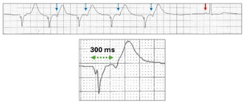
With an idioventricular run, inverted retrograde P waves can be seen either in the ST segment or T wave indicating that the ventricular wave of depolarization has traversed the conducting system and propagated retrograde to the atria via the AV node referred to as VA conduction (blue stippled arrows).
Unlike AV conduction which is robust, VA conduction is fragile and as the ventricular rate increases, VA blocks such as 2:1 occur (section 11.7).
Junctional ectopic/rhythm
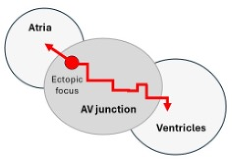
With junctional rhythm, there are two scenarios of retrograde P waves.
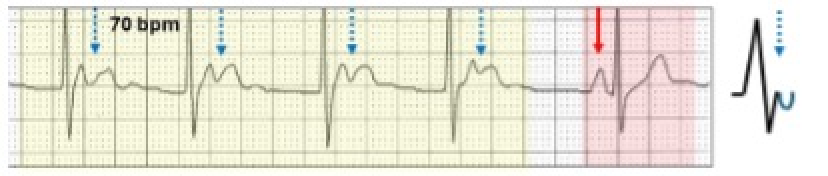
The inverted P wave follows the QRS. The ectopic focus lies low in the AV junction, allowing the anterograde wave to depolarize the ventricles well before the retrograde wave slowly traverses the AV junction to depolarize the atria (red arrows).
The inverted P waves follow the QRS and lies in the ST segment/T wave.
Sinus rhythm (red highlight, red arrow) and a junctional escape rhythm (yellow highlight) with the inverted P waves (blue stippled arrows, blue inverted half circle), lying within the T waves.
The inverted P wave precedes the QRS. The ectopic focus lies high in the AV junction allowing the retrograde wave to rapidly depolarize the atria first, then slowly traverses the AV junction anterograde to depolarize the ventricle (red arrows).
Inverted P waves with short PR intervals.
Sinus rhythm (red highlight, red arrow) and a junctional escape rhythm (yellow highlight) with the inverted P waves prior to the QRS and the PR interval is 80 ms. (blue arrows, blue inverted half circle).
Echo beats or reciprocal beats are propagating electrical complexes that return and reactivate their site of origin. For teaching, it is easier to remember or say echo beats, although reciprocal beats are a more precise description. They are great mimickers and can be very hard to diagnose even when the footprints are recognised. For this reason, echo beats are frequently missed or more likely misdiagnosed. An echo beat will occur if the critical timing of a retrograde P wave allows it to propagate anterograde to the ventricle. As with retrograde conduction, the most common initiating focus is a junctionalectopic or rhythmalthough atrial ectopics, ectopic atrial rhythms, ventricular ectopics,ventricular pacing and sinus rhythm with a prolonged PR interval may all generate echo beats with appropriate timing.
To generate echo beats, the impulse must be propagated retrograde to the atrium and then anterograde to the ventricle. To do this, dual AV nodal pathway physiology may be required. A single reentrant conducted atrial complex is seen as an echo beat, whereas a continual circus movement is a reentrant rhythm or tachycardia. Because of the timing, they may demonstrate aberrant ventricular conduction, usually with a right bundle branch block configuration.
How are echo beats created?
Junctional ectopic or slow junctional rhythm
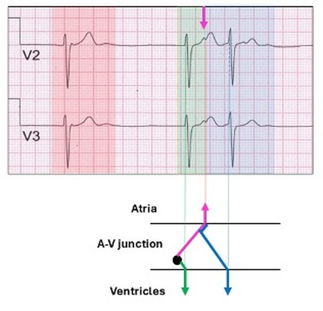
Slow junctional rhythm without retrograde conduction (red highlight).
The next complex (green highlight) has both anterograde conduction to the ventricle and retrograde conduction to the atrium (pink arrows).
The atrial impulse can now conduct anterograde to the ventricle via the previously blocked and now non-refractory AV pathway (blue arrow, blue highlight), resulting in an echo beat (blue highlight).
If the echo P wave is very premature, it may conduct to the ventricle with aberrant ventricular conduction.
An inverted P wave (yellow highlight, pink arrow) conducts during the zone of aberrancy, resulting in a broad QRS with a right bundle branch block configuration.
A similar example of a junctional rhythm with echo beats mistakenly called ectopics.
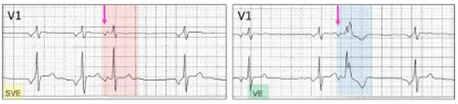
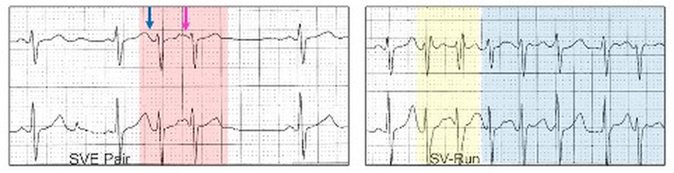
Left: Echo beat (red highlight) with a biphasic P wave (pink arrow) and an identical QRS/T to the native rhythm and called an atrial ectopic (SVE, yellow highlight).Right: Echo beat (blue highlight) now conducts with a right bundle branch block aberrancy and called a ventricular ectopic (VE, green highlight). Although these are identical to atrial ectopics, the presence of an ectopic atrial or junctional rhythm suggests echo beats as the conducted junctional rhythm avoids the fast pathway.
Atrial ectopic
To generate an echo beat, the ectopic should be premature and the atria non-refractory to the retrograde conduction. The mechanism involves dual AV nodal pathways. It may be impossible to differentiate echo beats from either atrial couplets or atrial interpolated beats and the diagnosis depends on differing P waves, which is usually very subtle
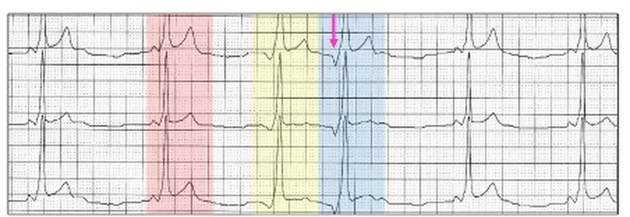
Sinus rhythm and an atrial ectopic (yellow highlight) with an upright P wave (blue arrow). Earlier in the tracing, an atrial ectopic (red highlight) is followed by a beat with an inverted P wave (pink arrow) and likely to be an echo beat.
If the atrial ectopic is very premature then it may be conducted with aberration.
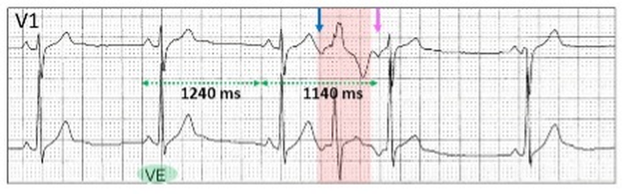
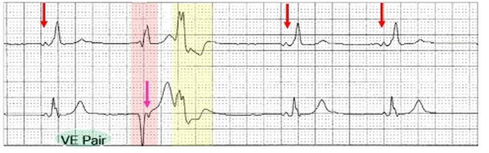
The broad QRS (red highlight) is called a ventricular ectopic (VE, green highlight) and has an rsR’ configuration and is preceded by an inverted P wave (blue arrow). This is an atrial ectopic with aberrant ventricular conduction. Following is an echo beat (pink arrow) which conducts to the ventricle with a narrow QRS. This cannot be atrial interpolation as the sinus cycle is longer (1240 ms) than the cycle with the embedded ectopic (1140 ms).
If dual AV nodal pathways are required for echo beats, could a combination of an AV nodal and pre-excitation pathways do the same thing?
Sinus rhythm with preexcitation (red highlight). An atrial ectopic conducts to the ventricle via the accessory pathway (yellow highlight) and retrograde to the atria (pink arrow) via the slow pathway as the fast pathway is refractory. The fast pathway in now able to conduct with an echo beat (blue highlight). If a tachycardia is initiated by such a mechanism, this is called an antidromic AV reentry tachycardia which is one of the unusual reentry tachycardias associated with Wolff-Parkinson-White preexcitation.
Ventricular ectopic
With appropriate timing, a ventricular ectopic with retrograde conduction can result in an echo beat. Again it is likely that dual AV nodal physiology is involved and a junctional beat precedes the ventricular ectopic, rendering the fast pathway refractory.
Sinus bradycardia (red arrows) with a junctional escape (blue arrow) followed by a ventricular ectopic (red highlight) and slow pathway retrograde conduction to the atria (pink arrow) followed by anterograde conduction. The junctional beat sets up the appropriate refractory periods and conduction times.
Another example of an atrial or junctional ectopic (blue arrow), prior to a ventricular ectopic (red highlight) and an echo beat (pink arrow).
Sinus rhythm (red arrows). A junctional ectopic (blue arrow) precedes a ventricular ectopic (red highlight) with retrograde conduction (pink arrow) and an echo beat.
Echo beats from a ventricular focus can be difficult to differentiate from couplets.
The report was a ventricular couplet (green highlight) with pre-excitation. There is a narrow QRS ventricular ectopic (red highlight) with fast pathway retrograde conduction (pink arrow) and anterograde slow pathway conduction with aberrant ventricular conduction.
Interpolated ventricular ectopics and echo beats may occur in the same tracing.
Left: Sinus rate (red arrows) 93 bpm (640 ms) and a ventricular ectopic (red highlight) which is interpolated (yellow highlight). Right: At a slower rate of 46 bpm (1300 ms), the ventricular ectopic has retrograde conduction and an echo beat (pink arrow).
Can slow pathway conduction create an echo beat?
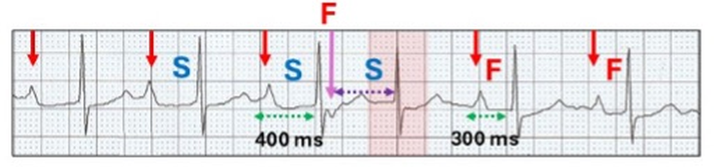
Sinus rhythm (red arrows) with a prolonged PR interval (400 ms) due to slow pathway conduction (S). With recovery of the fast pathway, there is retrograde conduction (pink arrow, F) and an echo beat via the slow pathway (red highlight). With a pause in fast pathway conduction, there is a return to a shorter PR interval, albeit still slow (300 ms).
The genesis of AVNRT
With appropriate timing, echo beats can replicate, creating a reentry circuit.
Left: (red highlight). Atrial ectopic (blue arrow) generates an echo beat (pink arrow). Right: An earlier complex (yellow highlight) conduct with minor aberrant ventricular conduction and initiates a reentrant tachycardia (blue highlight).
With degenerative disease in the AV junction, a “slowly” conducting reentry pathway can be created on the ECG. Because of delayed conduction, Wenckebach block and refractoriness results in short runs. Such ECGs provide a window into the mechanisms by which the circus movements of the faster AVNRT are established.
Here is an example.
Get out your callipers. Put in your coloured arrows and highlight and see if you can create the reentry circuit.
My interpretation follows.
Sinus bradycardia (red arrows) with first degree AV block (240 ms) and a bundle branch block.
Short run of a tachycardia (yellow highlight) with inverted P waves (pink arrows)
Retrograde conduction with the first inverted P wave (pink arrow) 420 ms after the onset of the sinus generated QRS.
The retrograde P wave conducts to the ventricle along the slow pathway ( S1, 320 ms) as an echo beat .
Once again there is anterograde conduction this time via the fast pathway (red highlight, F1) resulting in an inverted P wave (broad purple arrow)
The cycle is repeated with F2, S2, F3 (red highlight, broad purple arrows).
After S4, there is no retrograde conduction (red highlight, purple shadowed stippled P wave) and the reentry rhythm is abruptly terminated. This results from an increasing AV nodal Wenckebach block in the slow pathway (S1 320 ms to S4 440 ms).
Now imagine this with fast AV/VA conduction and you have AVNRT.
As its name implies, AVNRT is a reentrant junctional or supraventricular tachyarrhythmia which involves the fast and slow pathways within the AV node creating a self-perpetuating circus movement. It can be divided into typical (slow-fast) or atypical (fast-slow) as well as several rarer forms related to more than one slow or fast pathway with similar electrophysiological properties. On the ECG, they can be identified and differentiated by the positioning of the P wave in relation to the QRS complex, which in turn is related to the direction of the re-entrant AV nodal circuit. However, in about 60% of cases, the P wave is buried in the QRS/T and cannot be identified on the surface ECG.
Retrograde conduction is defined as conduction from an ectopic site to the atrium via the AV node or accessory pathway and referred to as VA conduction. II results in a P wave configuration which differs from an anterograde P wave, and in most ECG leads is inverted. The site from where the impulse originates can be the AV node, Bundle of His, distal conducting system or the body of the ventricles including ventricular pacing. On the ECG, the QRS complex usually precedes the inverted retrograde P wave but on occasion may follow it.
In 1970, I commenced work as a “novice” cardiologist at The Royal Melbourne Hospital. Training at that time was learning how to recognise the diastolic murmur of mitral stenosis and making sure the ECG and chest x-rays were the correct way up. As this was prior to coronary artery surgery, stenting and echocardiography, the ECG was a highly respected tool for the diagnosis of many conditions. I was fortunate to befriend a number of the gurus of ECG interpretation who taught me to look into the soul of an ECG. Today, even though the ECG is the first investigation performed by a cardiologist, the art of ECG interpretation has been lost because we depend on the new tools for cardiac diagnosis.